[Top] [Prev] [Next]
7.2 The 24-Bit Raster Data Model
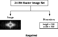
The 24-bit raster image set, or RIS24, data model supports two primary data objects: two-dimensional 24-bit raster images and dimensions. The primary member of the set is the 24-bit raster image, a two-dimensional array of pixels or picture elements. Each pixel is represented by three 8-bit numbers of image data. An optional compression method describes the method used, if any, to compress the image. Figure 7a shows the contents of a 24-bit raster image set.
FIGURE 7a - 24-Bit Raster Image Set Contents

7.2.1 Required 24-Bit Raster Image Data Set Objects
All 24-bit raster images must contain image data and a dimension record. These objects are created by the HDF library using information provided at the time the image is written to file.
7.2.1.1 24-Bit Raster Image Data Representation
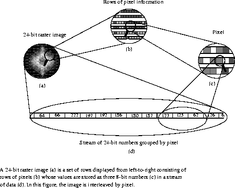
The 24-bit raster image object contains a set of 24-bit pixel values, each of which has three 8-bit components; one for the red, one for the green, and one for the blue color component of the image. These values, referred to as RGB values, are arranged in one of three specific ways, as described in Section 7.2.2.2 on page 249. The pixel values are arranged in rows, painted from left-to-right, top-to-bottom. As each pixel in a 24-bit image is represented in the image data by three 8-bit numbers, palettes are unnecessary and are not included in the 24-bit raster data model.
As an example, consider a stream of 24-bit numbers representing a raster image (Fig. 4.1a). To display the image, the color associated with the first number in the data stream appears in the upper left corner of the image. The remainder of the first line is then painted from left-to-right using as many values from the data stream as necessary to complete the line. The remainder of the rows are similarly painted from left-to-right, top-to-bottom until every value in the data stream appears as one pixel in the image.
FIGURE 7b - The Numerical Representation of a 24-Bit Raster Image

7.2.1.2 24-Bit Raster Image Dimension
The dimensions of an image are the height and width of the image in pixels.
7.2.2 Optional 24-Bit Raster Image Data Set Objects
7.2.2.1 Compression Method
The only 24-bit compression method currently available in HDF is the JPEG algorithm . The applicable HDF compression tags are COMP_JPEG, and COMP_NONE. (See Table 7A.) The HDF tags COMP_JPEG and COMP_NONE are defined as the values 2, and 0 respectively in the "hdf.h" header file.
TABLE 7A - 24-Bit Raster Image Compression Method List
JPEG Compression
The JPEG compression method is a lossy compression algorithm whose use is recommended for photographic or scanned images. Using JPEG compression to reduce the size of an image changes the values of the pixels and therefore may alter the meaning of the corresponding data.
For more information on the JPEG algorithm, refer to Chapter 6, 8-Bit Raster Images (DFR8 API).
7.2.2.2 Interlace Modes
Because graphics applications and hardware devices vary in the way they access image data, HDF supports three interlace formats. By storing an image using a format that is consistent with the expected application or device, it is possible to achieve substantial improvements in performance.
HDF provides three options for organizing the color components in 24-bit raster images. These options consist of pixel interlacing, scan-line interlacing, and scan-plane interlacing. (See Figure 7c.) Storing the color components grouped by pixel, as in red-green-blue, red-green-blue, etc., is called pixel interlacing. Storing the color components by line, as in one row of red, one row of green, one row of blue, one row red, etc., is called scan-line interlacing. Finally, storing the color components grouped by color plane, as in the red components first, the green components second, and the blue components last, is called scan-plane interlacing. Unless otherwise specified, the HDF 24-bit raster model assumes that all 24-bit images are stored using pixel interlacing.
FIGURE 7c - RGB Interlace Format for 24-Bit Raster Images

An interlace format describes both the physical format of an image as it is stored in memory and in the file. When writing to a file, HDF stores a 24-bit image using the same interlace format as it has in memory. However, when reading from a file, it is possible to make the in-core interlacing mode different from that used in the file. The following table contains a summary of the interlacing format available in the DF24 interface.
TABLE 7B - 24-Bit Raster Image Interlace Format
[Top] [Prev] [Next]
hdfhelp@ncsa.uiuc.edu
HDF User's Guide - 07/21/98, NCSA HDF
Development Group.


