Displacement Mode Shape
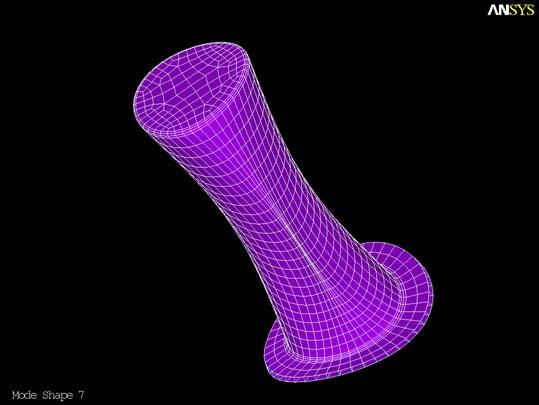
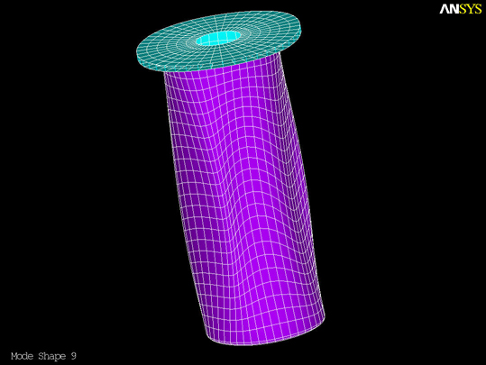
The IDEAS solution provided for 35 mode shapes between the frequencies of 0 and 3500 Hz. In order to test if the model was being re-created accurately, animations of the first two non-rigid body displacement modes (7 & 9) were created. This step helped verify the transfer of nodal data and element connectivity.
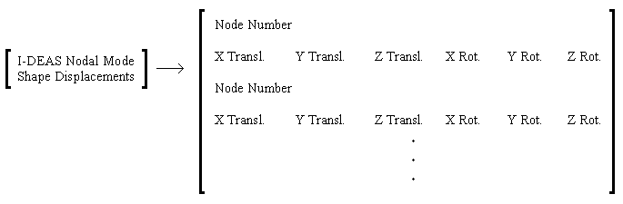
The process began with the output file from I-DEAS that provided the displacements at each of the nodes in the FE model, for all 35 fully displaced mode shapes.
The next step was to sort through this data set to acquire the data for each of the mode shapes. Here is the Matlab Code (FE_mode_disp_XYZ_coord) that does all of the sorting of the and the two mode shape data files that result from running this code.
The IDEAS Documentation may be
referenced for more information about the output file.
|
|
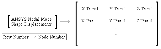
For the case of making the movies, the nodal rotation were ignored, therefore only the X-Y-Z displacements were considered. The data was then formatted for ANSYS as follows:
 |
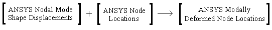
These nodal displacements were added to the original node locations to obtain the nodal locations in order to create the deformed mode shapes.
 |
Using these new node locations, the same process for meshing was used to create the deformed mode shape in ANSYS.
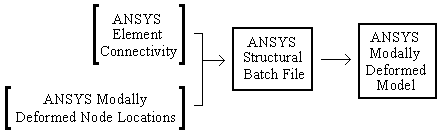 |
And finally the result is a cylinder that is deformed in the designated mode shape deformation:
 |
|
Displacement Mode 7
|
 |
|
Displacement Mode 9
|