 |
(1.1) |
by
Ronald D. Kriz
Associate Professor
Engineering Science and Mechanics
Virginia Polytechnic Institute and State University
Blacksburg, Virginia 24061
The problem under consideration is the stress analysis of symmetric laminates, including thermal-moisture and edge effects. In this study a linear-elastic analysis for both mechanical and thermal-moisture loading is performed using a finite element model (FEM). The applied load, whether mechanical or thermal- moisture, is assumed to be steady and uniform across the laminate. A typical symmetric laminate is shown in Fig. 1, where L> b >> H, and each layer is referred to as a lamina.
For long prismatic bars under the influence of applied strain at the ends or exposed to a uniform change in temperature-moisture conditions, it is assumed that the strain removed from the ends is independent of position along the bar, i.e. generalized plane strain. For strains independent of coordinate x, the strain-displacement relations are written as functions of the y and z coordinates only.
 |
(1.1) |

Figure 1. Typical Laminate Geometry
The equilibrium equations, neglecting body forces, reduce to
 |
(1.2) |
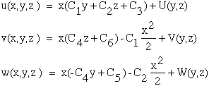
Integrating (1.1) yields the displacement field for plane strain.
 |
(1.3) |
where C1 and C6 and (U,V,W) are unknown constants and functions respectively which are to be evaluated give the boundary conditions.
x-y plane:
 |
(1.4a) |
 |
(1.4b) |
where the bar over the x is a relative position chosen here as zero.
Substituting (1.4) into (1.3) yields
 |
(1.5) |
 |
(1.6) |
The reduced form of Equations (1.3) are
 |
(1.7) |
where C3 is equal to the uniform applied axial strain xx .
The traction free boundary conditions along the laminate free edge are
 |
(1.8) |
and along the top and bottom laminate surfaces.
 |
(1.9) |
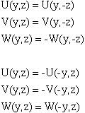
The antisymmetric conditions of Equations (1.6) yield the following restrictions on the displacement fields.
 |
(1.10) |
The symmetry conditions of Equations (1.6) yield
 |
(1.11) |
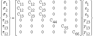
The boundary value problem represent by Equations (1.7) through (1.11) is independent of material behavior. For an orthotropic lamina oriented in the principle material directions, the three-dimensional constitutive relationships are
 |
(1.12) |
and with the 1 axis perpendicular to a plane of isotropy
 |
(1.13) |
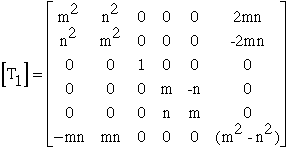
For a coordinate transformation in the 1-2 plane, rotation about the 3 axis, the transformed stresses and strains are
 |
(1.14) |
Such that the constitutive relationship in the xyz coordinates are
 |
(1.15) |
 |
(1.16) |
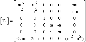
The transformation matrices are
 |
(1.17) |
 |
(1.18) |

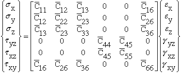
and the transformed constitutive relationship in the (x,y,z) coordinate system is obtained by expanding Equations (1.16).
 |
(1.19) |
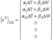
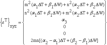
For a uniform temperature distribution, DT, and a uniform moisture absorbed weight gain, DW, the lamina principal thermal-moisture strains are
 |
(1.20) |
 |
(1.21) |
The strains in Equations (1.14) and (1.19) are referred to as the mechanical or elastic strains, {e}xyz , since these strains are used to calculate the elastic strain energy. The basic assumption in the thermal formulation is that the total strain {eo}xyz is the summation of the stress related mechanical strain {e}xyz and the free thermal-moisture strains {eT}xyz.
 |
(1.22) |
 |
(1.23) |
The basis of the finite element method is the representation of a body or structure by an assemblage of subdivisions called "finite elements". Figure 2a shows a typical triangular finite element discretization of the quarter- section shown in cross-hatched in Figure 1b. Simple functions are then chosen to approximate the distribution or variation of the actual displacements over each element. These functions are usually referred to as "displacement functions". A variational principle of mechanics, such as the principle of minimum potential energy, can then be used to obtain the set of equilibrium equations for each element. The equilibrium equations for the entire body are then obtained by combining the equations for the individual elements in such a way that continuity of displacements is preserved at the interconnecting nodes. The equations are modified for the give force or displacement boundary conditions and then solved to obtain the unknown displacements. Desired solutions in terms of strains and/or stresses can then be determined. For a more complete explanation of the method summarized above we refer the reader to Bathe and Wilson, Ref[1].
The constant-stress / constant-strain triangular element consisting of three nodes, Fig. 2b, was chosen for this problem. The displacement functions are linear relations with the same functional form as the generalized plane condition, recall Equations (1.1), (.13) and (1.7) in sections 1.1 and 1.2.
 |
(1.24) |

Displacement functions (1.24) satisfy Equations (1.7) and yield constant strains when substituted into Equations (1.1).
The quarter-section shown cross-hatched in Figure 1b is replaced by triangular elements as shown in Figure 2a. The value of xx is the prescribed uniform strain loading over all elements and is normal to the finite element grid yz-plane. When the assumed linear displacement functions in Equations (1.24) are substituted into Equations (1.1) then the resulting constant strains are
 |
(1.25) |
and the a's in Equation (1.25) can be evaluated in terms of displacements at the three nodes of each element. For an arbitrary finite element k, Figure 2b, the displacements at the three nodes are
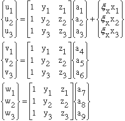 |
(1.26) |
The a's that are needed for Equations (1.25) are found to be
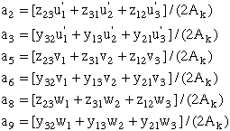 |
(1.27) |
 |
and
 |
(1.28) |
Noting that x1 = x2 = x3 are equivalent initial coordinates then the xx xi terms are either multiplied by
 |
(1.29) |
Consequently the first two of Equations (1.27) reduce to
 |
(1.30) |
In a similar fashion the remaining equations relating the nodal displacements with the a's are obtained such that the strains are obtained.
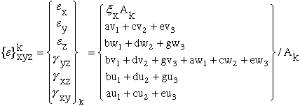 |
(1.31) |
where
 |
(1.32) |
Equations (1.31) represent the strain-nodal displacement relations of the k-th finite element for a prescribed uniform strain, xx.
Consider xx to be an unknown uniform strain over the quarter-section of Figure 2a. Let {eo}k represent the total strain in the k-th element, {eT}k represent the thermal-moisture elemental strain, and {e}k represent the mechanical strains giving rise to stresses. Letting {eo}kxyz have the functional form of Equations (1.31) then the mechanical elemental strains are
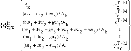 |
(1.33) |
Equation (1.33) represents the strain-nodal displacements relations when the strain due to a change in the thermal-moisture conditions must be determined.
The total potential energy, y, of a system is the sum of the elastic strain energy, U, and the potential energy of the external loads, W.
 |
(1.34) |
The strain energy over the k-th element is
 |
(1.35) |
For an element of unit thickness and constant strain
 |
(1.36) |
The external work over the k-th element is
 |
(1.37) |
Combining
 |
(1.38) |
The necessary set of element equations can be obtained by minimizing y with respect to each displacement.
 |
(1.39) |
For the prescribed uniform strain xx loadcase.
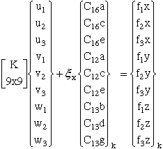 |
(1.40) |
For the unknown thermal-moisture strain,
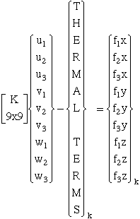 |
(1.41) |
The complete matrices for K, K' and thermal terms are listed in Appendix C.
Since the "Out-of-Plane" strain normal to the y-z element plane is either prescribed, xx, or solved for as an unknown, the two load cases are unique formulations. Although the formulation requires that each of load case must be solved for separately, the results can be superposed postmortem. A graphical schematic for both of these load cases are summarized in Appendix A, see Figures A1 and A2. Fortunately the material properties modeled in this computer program, are linear elastic which justifies the use of superposition of the element stresses after the solution of the two load cases separately.
Although the superposition of xx (prescribed) and (unknown) can not be realized together in the same program execution, superposition of either of these two conditions is possible with a mechanical load prescribed at nodes as nodal forces or displacements within the plane perpendicular to the direction of the "Out-of-Plane" strain xx. Consequently this computer program can solve an additional problem of stress distributions in the laminate x-z plane, where the y-axis is the generalized plane strain axis, see Figure 3. An applied mechanical strain along the x-axis is simulated by prescribing nodal x-axis displacements and the resulting plane strain along the y-axis can be prescribed within the same program execution. This way it is possible to avoid two separate runs and superposing results postmortem. Unfortunately the coordinates defining the elemental plane and axis of plane strain have been changed which can lead to some confusion. Hence the notation used in the computer program was made more general so that either the free

edge problem as defined in Figure 2 (yz-plane) or the problem defined in Figure 3 (xz-plane) can be solved with this computer program. The more general notation is graphically defined in Figure 4, where the N-axis is always referred to as the axis (N)ormal to the elemental H-Z plane and the z-axis is always coincident with the plate thickness. The H-axis can therefore be either the y-axis for the "Free-Edge" problem or the x-axis for the problem graphically defined in Figure 3.

With the superposition of nodal loads and "Out-of-Plane" strain in the same computer execution, as graphically defined in Figure 4, it will be possible to calculate the redistribution of stresses in a laminate with a ply crack and interply delaminations.
The reader may also want to compare stress distributions predicted by this program with previous results of Pipe and Pagano, Ref[3,4,5]. For comparison there is also a pertubation solution for predicting interlaminar solutions near a laminate "Free-Edge" Ref[6]. This particular computer program was used calculate residual stress distributions in a quasi-isotropic graphite/epoxy laminate subject to dehydration ("Dry") and saturation ("Wet") conditions, Ref.[7]. A Web summary of results of this research compares stress distrubtions, precdicted by this FEM "Free-Edge" computer program with experimental statistical results. These numerical and experimental results together with a Scanning Electron Microscope (SEM) investigation predict and visually demonstrate the influence of residual stresses and 90 degree ply cracks on the laminate fracture strength. Statistically sigmificant populations confirm these predictions.
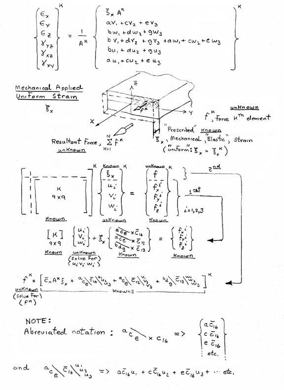
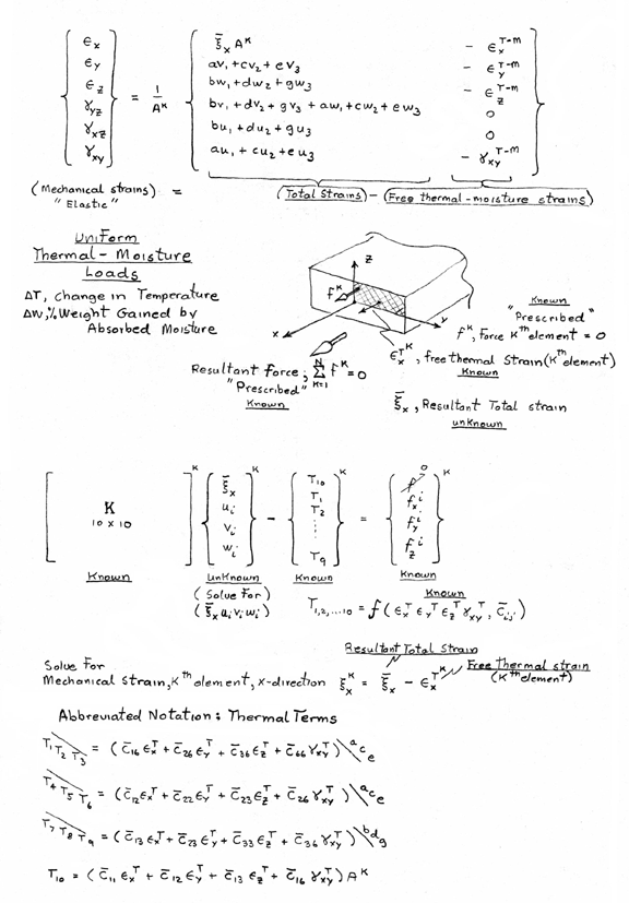
Two types of conditions exist for the out-of-plane strain xx : 1) xx prescribed and 2) xx unknown.
Schematic summary of prescribed out-of-plane strain, xx.
Schematic summary when out-of-plane strain, xx, is unknown.
Recall equation 1.31
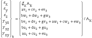 |
(B1) |
and expand equation B1 into two matrices: [B] which is multiplied by a vector of unknown nodal displacements and applied out-of-plane strain.
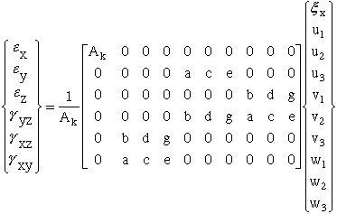 |
(B2) |
The abbreviated notation for equation B2 is rewritten
 |
(B3) |
With the [B] matrix defined, the form of the elemental stiffness matrix as defined in section 1.7 can be rewritten here in terms of the [B] matrix.
 |
(B4) |
Where the transformed stiffness matrix defined by equation 1.19 is rewritten here
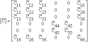 |
(B5) |
Post multiplying the stiffness matrix by the [B] matrix in equation B4 yields
 |
(B6) |
Multiplying this result with [B]T yields the final elemental stiffness matrix used by the finite element program. This 10x10 matrix is too large to be listed here in its' full matrix format so each of the individual terms are listed in Appendix C.
The creation of each term of the elemental stiffness matrix, as outlined in Appendices A and B are listed here for reference. Figure A1 shows a schematic outline with abbreviated notation on how to calculate the elemental stiffness terms for a 9x9 matrix and a 10x10 matrix with knowns and unknowns noted in the hand written diagram. For this case the out-of-plane strain is a known quantity prescribed uniformly across the yz-plane. In this particular case only the terms of the 9x9 elemental stiffness terms are listed.
The same notation was used by Nagarkar and Herakovich, Ref [2], in a similar laminate "Free-Edge" problem that studied nonlinear behavior. In Appendix B of the this VPI&SU report there are two typographical errors in Appendix B for K35 and K68. These errors have been corrected and the correction listed below.
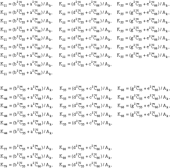 |
(C1) |
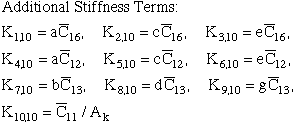
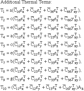
The creation of the thermal terms requires that the out-of-plane strain be included as an unknown along with the nodal displacements for each element as shown in the schematic diagram shown in Figure A2. In this case when the out-of-plane strain is unknown the out-of-plane elemental force is known to be zero, the elemental stiffness matrix becomes a 10x10 matrix with an additional row and column, and the additional thermal terms {T}k are written in abbreviated format. In Appendix A the additional elemental stiffness matrix terms and the thermal terms, that were listed in abbreviated notation, are listed here in non-abbreviated format.
 |
(C2) |
 |
(C3) |